How Do Flex PCBs Perform in High-Flexure Applications?

Flex PCBs Perform in High-Flexure Applications
As one of the most versatile PCBs available, flex PCBs have a wide range of uses. They can be bent and twisted to fit into tight spaces, which is something that standard rigid PCBs cannot do. They can also withstand high-flexure applications, such as those found in automotive and medical devices. However, to ensure that a flex circuit board can withstand these kinds of conditions, it must be designed properly.
A good flex PCB will have the correct layer architectures, materials, and surface finishes to maximize its strength and performance. It will also be built with proper bending radius and bend angle dimensions, allowing it to maintain its structural integrity during high-flexure conditions. To get the best results from a flex circuit, it’s important to choose a turnkey PCB manufacturer that specializes in them. This will ensure that the flex pcb is made with the highest-quality materials, and that it’s built using the latest technologies and techniques.
In order to improve a flex circuit’s reliability, it’s essential to design it with the right copper thickness and trace width. A higher copper thickness can cause a flex circuit to become more rigid. It can also result in higher power losses due to excessive copper area. To prevent this, the copper thickness should be minimized as much as possible.
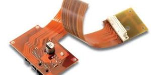
How Do Flex PCBs Perform in High-Flexure Applications?
Another important consideration is to keep the flex area free of discontinuities like vias, cut-outs, and slits. These can lead to stress and cracks that could compromise a flex circuit’s reliability. It is also critical to avoid placing these elements near the neutral bending axis of a flex circuit. It’s also a good idea to stagger the conductors that traverse a flex area. This will minimize stress that can damage the copper circuits.
Using a high-grade Rolled Annealed (RA) copper foil can help a flex circuit resist fatigue. This is because RA copper can stretch further before fatigue cracking occurs than unannealed copper. It can also be more springy in the Z direction, which makes it perfect for a flex circuit that will be subjected to repeated creasing and movement.
A flex circuit’s plating process is another crucial aspect to consider. It’s important to understand whether panel or pad-only plating (button plating) is the better option for a flex circuit. Button plating uses a smaller amount of copper and improves etch yields in small traces. However, it can be more expensive than panel plating.
Flex PCBs are prone to more movement and compression during manufacturing than rigid PCBs, which is why it’s crucial for engineers to follow IPC rules when designing them. Adhering to IPC standards like IPC-2221 can ensure that a flex circuit is efficient and durable. IPC-2221 establishes the general requirements for PCB design along with testing standards for different circuit parameters. In addition to following IPC guidelines, engineers should perform a thorough testing of the flex circuit for quality assurance. This will help prevent any issues that may arise during production or assembly.